Modular Robotics Universal Connection Scheme
Sept 2023 - Feb 2024
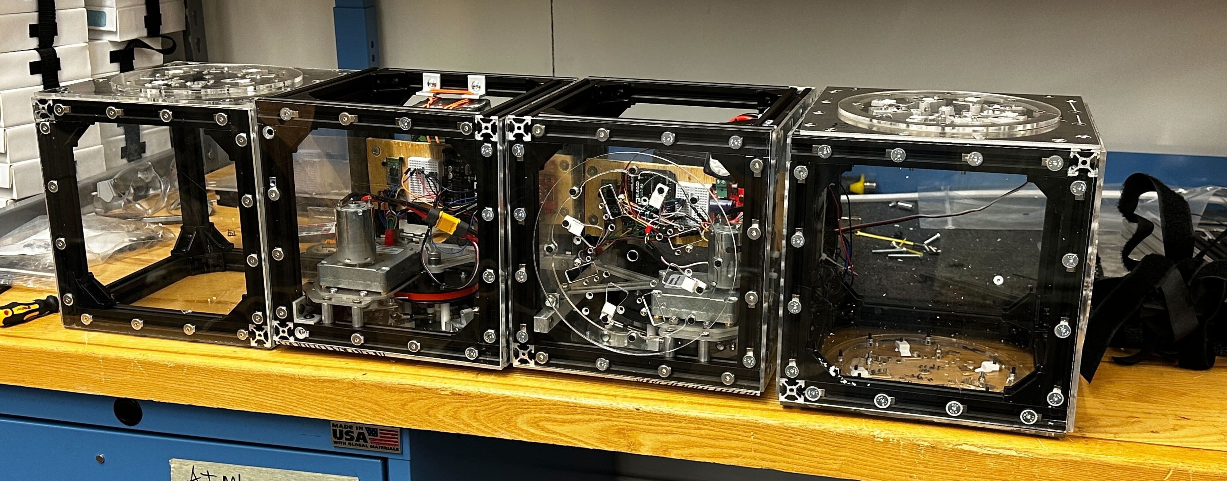
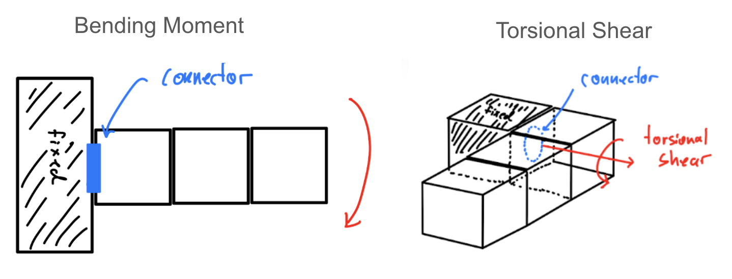
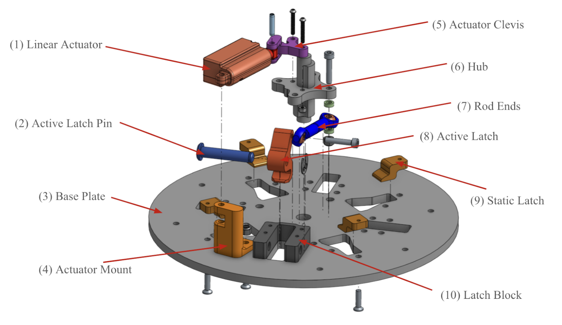
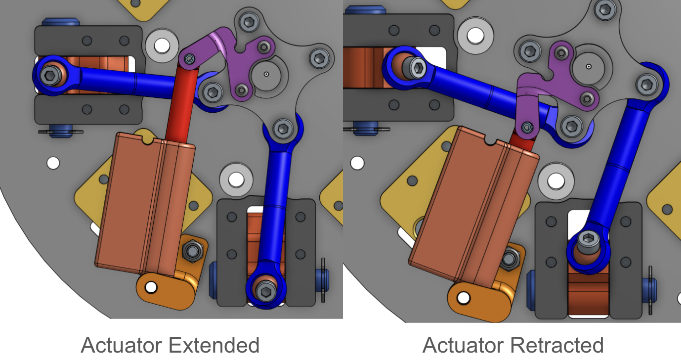
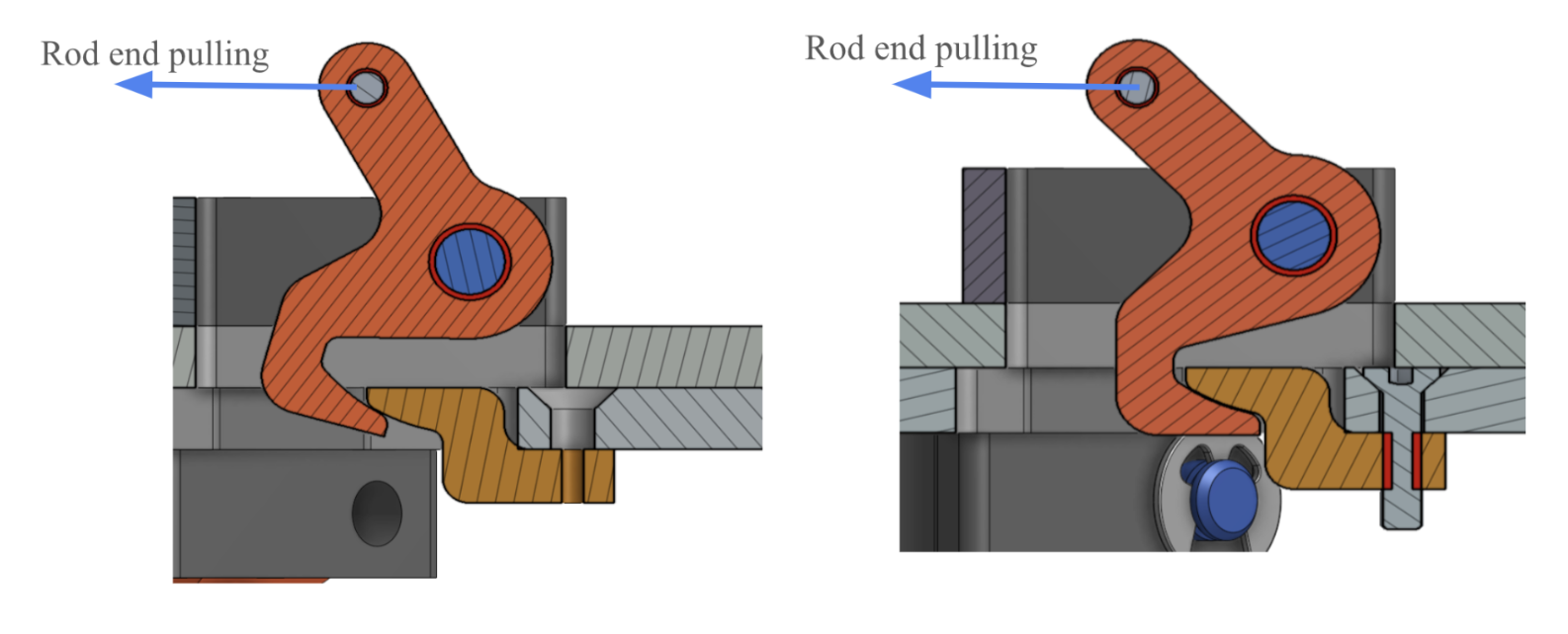
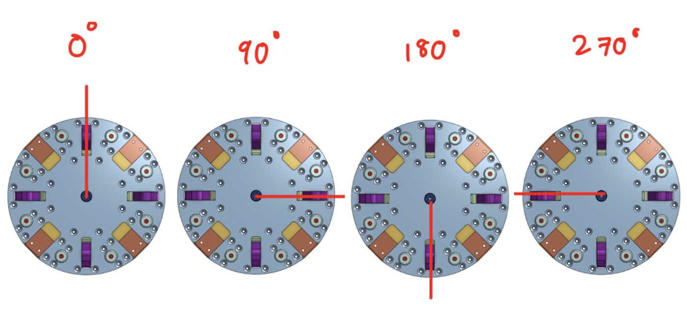
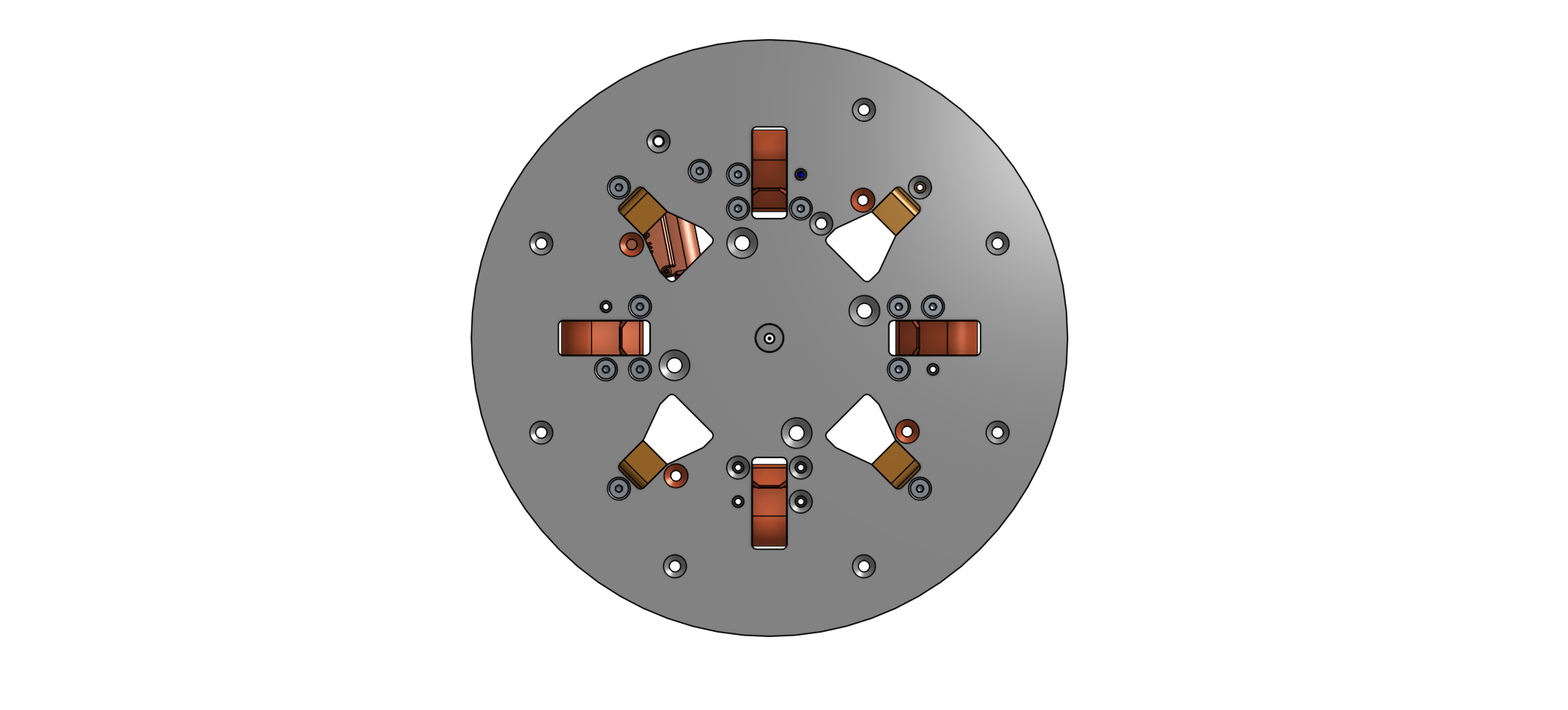
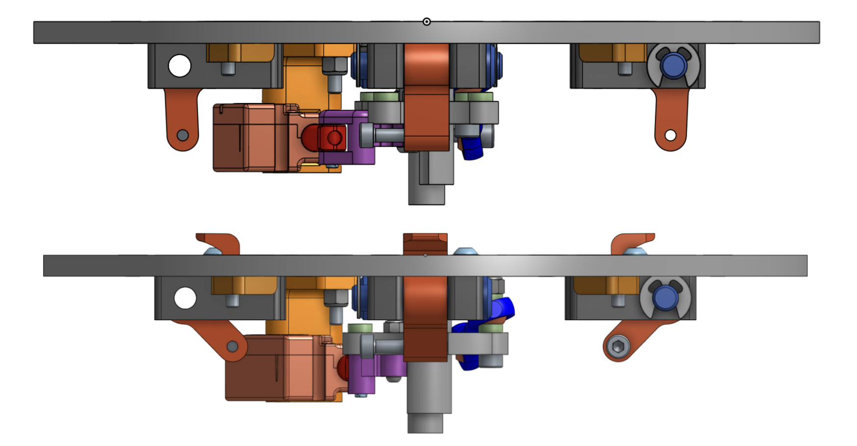
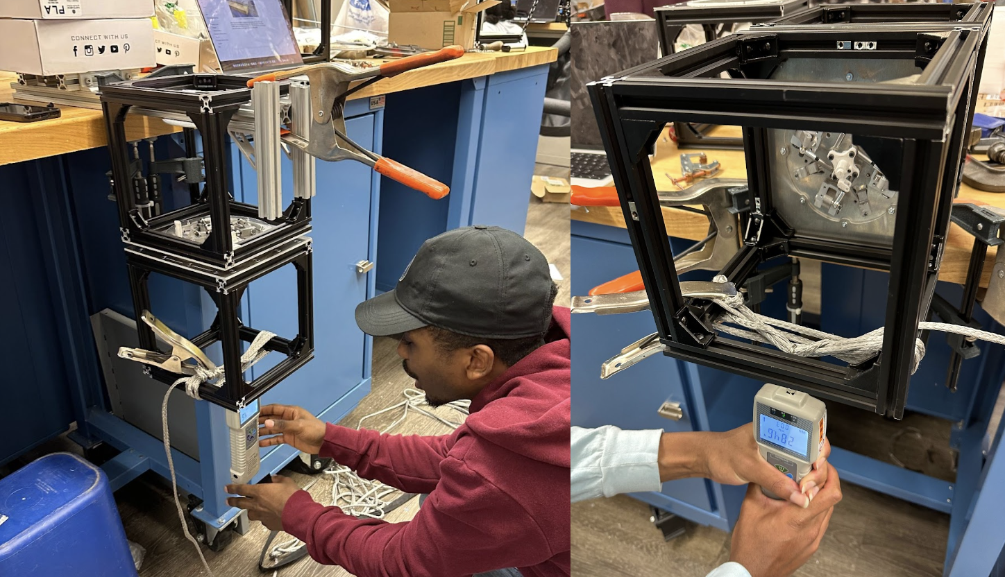
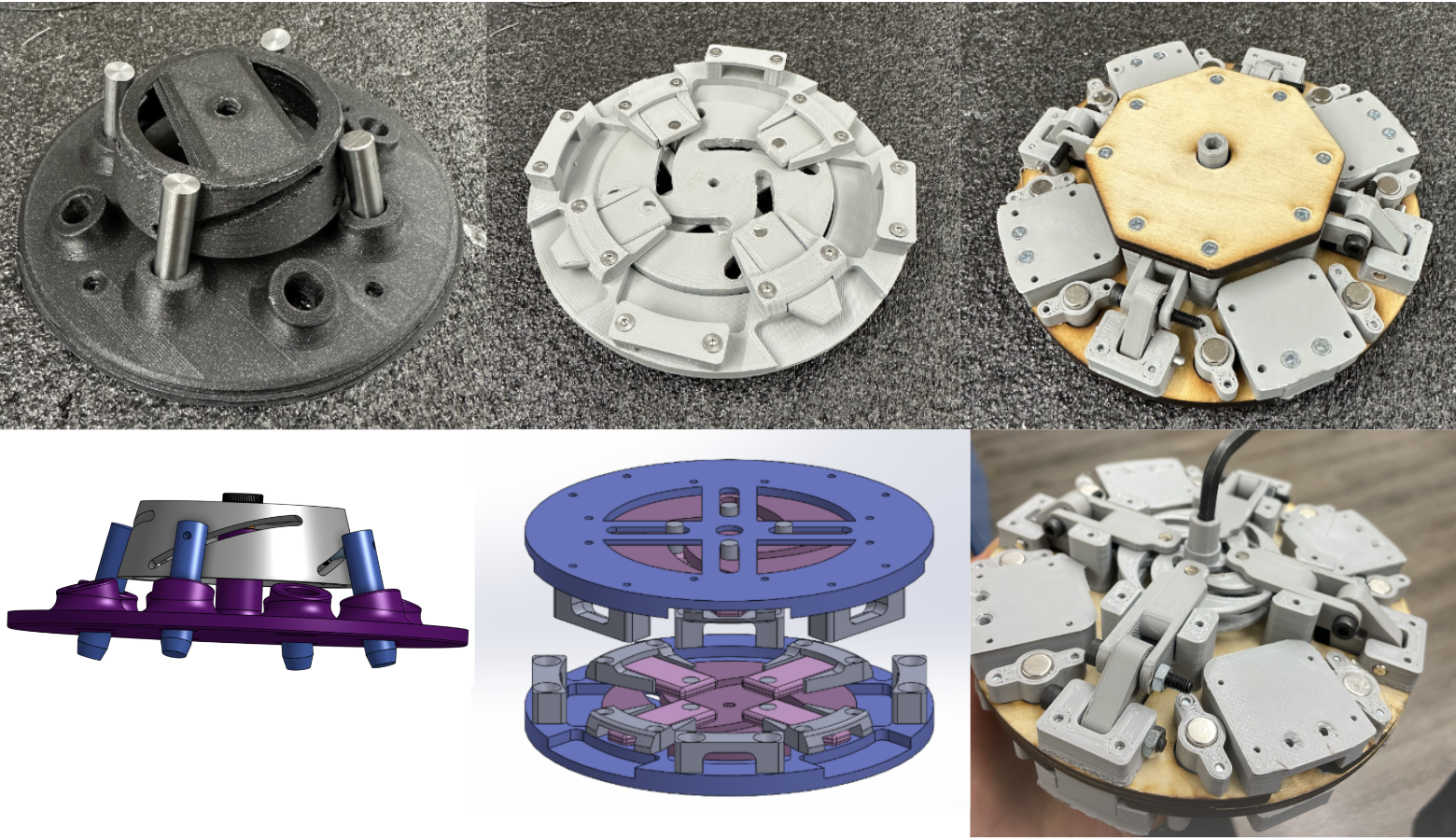
As a part of my senior mechanical engineering capstone project, I designed a subsystem which allowed cube-shaped robotic modules to interconnect in any orientation while being able to sustain high static loading conditions.